
An oven this size would be ideal for coating an axle, and an axle is an ideal candidate for powder coating.
1 Like
With the racks set up properly, the cabinet looks big enough to do wheels. Probably couldn’t do a set of 22" or bigger but my 16"ers would probably fit.
Wheels, bicycle and motorcycle frames, axles, etc.; anything made of metal can be coated. Very durable and colourful.
We have plans for hanging hooks, and a roll-in rack that you can take into the paint room, then roll into the oven.
There will be at least one shelf. This could be used to heat acrylic for molding wind shields and similar things.
Ok; picking up the insulation tomorrow. Does anyone have some sheet metal, between 28 gauge and 18 gauge? We need about 75-100 square feet of it.
We also need someone to 3D print a bezel for the controller.
I have been working on cutting out the pieces of metal for closing up the cabinet. Could use some help with that tonight.
We still need a heating element (208/240 volt single phase, 2300 to 3500 watts), a door gasket (220 inches long), two spring-loaded latches, and a power cord for 208/240 single phase 17 amps). Does anyone have any of these items to donate to the cause?.
We still need a heating element (208/240 volt single phase, 2300 to 3500 watts), a door gasket (220 inches long), two spring-loaded latches, and a power cord for 208/240 single phase 17 amps). Does anyone have any of these items to donate to the cause?.
Yes.
Give me specifications for what you want of the bezel and I’ll try and model something to print when I’m at the space tomorrow.
1 Like
I have an old built in oven in my garage that I plan to dump if I can ever get it out of my garage. However, if you just need
the elements, I will take them out and contribute them. I can do that tomorrow morning, and I plan to be at the space around three tomorrow.
The attachment is the instructions for the controller.
enter link description here
enter link description here
We have a TA4 type. Unfortunatly, the dimension diagram is very poor, so I am not sure whether the outside dimension is A x B or F x E. Maybe Bryan can measure it?
What would work best is a square bezel about 8mm wide that the controller fits into.
Thanks.
I think the dimensions are ExF,but the modeling software I’m using is parametric, so if it happens to be AxB, it’s a simple matter to adjust it. Best to get measurements before committing to a print.
But I’m suddenly a tad confused. Do we need a bezel to go around the face of the thing and get bolted to the cabinet, or something that snugs up behind the face, sandwiching the cabinet between face and bezel? Either one is doable, I just don’t want to model the wrong piece.
Unit is in the amazon box in the cabinet. Should be inside it’s own brown cardboard box.
We want a bezel around the unit to hide any uneven lines when we install it in the control box.
Okay, that makes sense. I’ll make it pretty then. I don’t have enough gas money to make it up to the space, so if somebody can grab some for-sure measurements for me (preferably in mm), that’d be great.
The outer bezel on the controller is 48mm x 48mm, and 8 mm deep. The body of the controller is 45mm x 45mm. So we need something about 61mm x 61mm, with a recess in it 6mm deep, 48mm x 48mm, and a hole in it 45mm square. Rounded corners are good, but square will work. Black is Ok, but anything except fuchsia is acceptable.
First pass at wiring diagram:
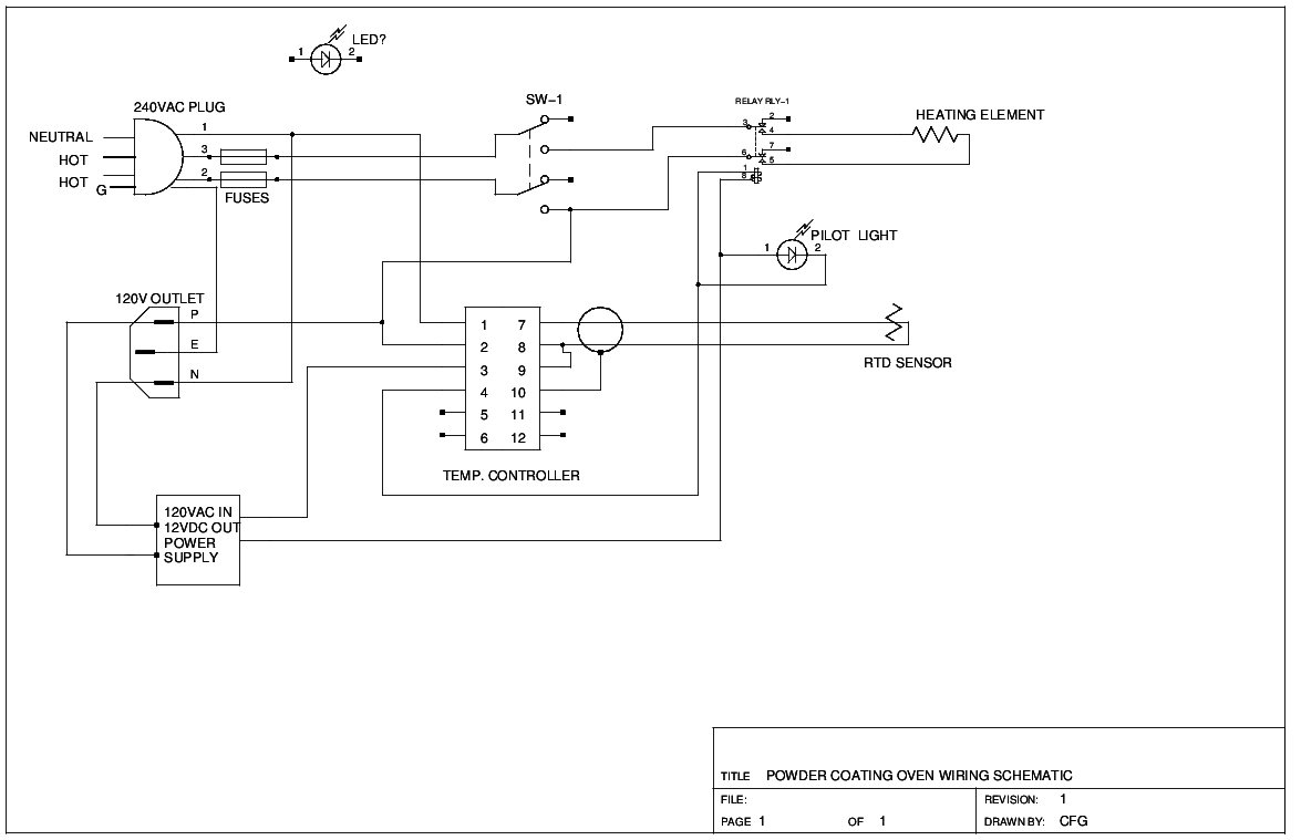
I have a wall wart for the 12VDC control power. We have all the other parts, except the switch and outlet.
Anyone want to build this?
A solid state relay would be preferable over an electromechanical for this.
I’d also suggest a contactor instead of a simple switch for the kinds of currents I expect here.
The relay that we have on hand is solid state type. The switch serves as a disconnect: contactors can weld, so they are not used as disconnects.
In that case the schematic is a bit misleading. Neither disconnects nor SSRs are double pole double throw.
Sorry for the confusion.
Ok; we have the insulation here. We need to pick up some sheet metal at Lowe’s. We can start work on the controller, the door, the door seal, and the insulation. Who can be here on Thursday (tomorrow)?
1 Like
I can be here tomorrow, but I have a lot of work. As such, I can help you when you need an extra pair of hands.
Ok; closed up the big hole in the door with some 16 ga stainless. Closed the two fan openings in the back of the cabinet. I am going to do the small opening in the door and the large filter opening in the back next.
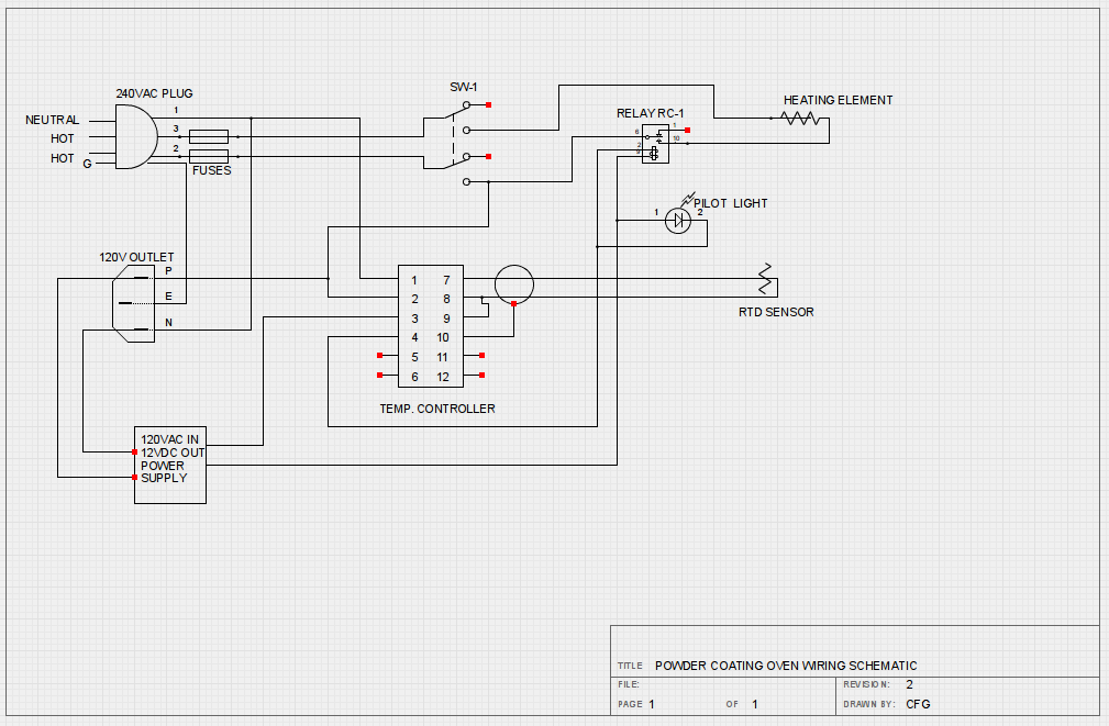
For the wiring this is where we stand:
Things we still need:
(1) Plug, 208V, single phase, w/ Neutral & Ground
(2) Fuses, __Amps, 250 volts
(1) Socket, 120 volt
(1) Switch, 50Amps, 250 volts, DPST
(1) High Temperature Cutout, 250 volts, 600 Degrees F.
(1) Timer Switch, 2 hours, 120v
(20’) Power Cable, 50A, 250 volts
Things we have:
(1) Power Supply, 120VAC in, 12 VDC out, 1.2A
(1) Temperature Controller
(2) Pilot Lights
(1) RTD Sensor
(1) Relay, Solid State, 208 VAC, 25A, 5-30 VDC control voltage
(2) Heating Elements (use one for now)
(1) Enclosure 8x8x6
We need some wire coat hangers to secure the insulation while we build the liner.
If anyone is at the Space you could strip out all the parts inside the control box. It is presently located inside the cabinet. The controls in it are for an old heater box. We are going to recycle the box, terminals, pilot lights, etc. Don’t throw anything out yet.
Insulation and liner next week. Come by on Tuesday night, and we can start work on it.
1 Like