We are continuing to work on the nitrogen laser on June 27.
I’m running late for this meeting.
We are continuing to work on the nitrogen laser on June 27.
I’m running late for this meeting.
I’m running late for this meeting.
Me too - anyone who is planning to attend please stand by. My ETA is 3 PM.
JAG “On Pagan Standard Time” MAN
Wow, we had a great turn-out today! Eight other people and I inched the project closer to completion. I had hoped for us to finish it today, and though we didn’t, we made good progress. Several of the people who attended this project were non-members who saw the event on an off-site page.
We have several optional configurations that we can use to complete this project. I like that we could swap out parts, to see what effect different components would have on the final result. We have four power supplies; three choices for cavity capacitor; we could operate under partial vacuum or attempt to operate at atmospheric pressure; we could run from a tank of nitrogen or try using atmospheric nitrogen. We also have lots of room for tweaking the design.
Work remaining to be done:
The bottom half of the laser cavity needs to be sealed against the copper sheets, opposite from the top half of the laser cavity. We are currently using silicone caulking, which might work, though it isn’t what I normally see used. As long as it does not leak significantly (and I doubt it would), we should be fine. We are taking the vacuum down to about 5 torr, or whatever we can get with our pumping equipment.
The polycarbonate sheet needs to be cut so we have end plates for the laser cavity. The end plates need to be fabricated with a hole (~2 cm) cut in the middle of the short dimension and brass burrs fit in the side to reach to the central hole. The central hole allows the UV laser beam to exit from the laser cavity (a beam about 1 cm wide at that point) and must be small enough for a transparent cover (such as a microscope slide) to seal it. We would use wax (that we still don’t have) to attach the microscope slide to the end plate. The burrs allow evacuation of the laser cavity and gas fill; I imagine one burr on each end plate.
The copper sheets forming the electrodes in the middle of the laser cavity need to be attached to one of our capacitor banks. We have at least two options currently for capacitor banks, and I think either of them would work to some degree. It would be nice if the copper sheets were soldered to a capacitor bank so we could easily remove it. Then, we could try out a different capacitor bank.
The 10-turn copper wire inductor needs to be soldered to either side of the vacuum cavity spark gap.
The triggering spark gap that Joel @JAGMAN is fabricating needs to be connected across the capacitor bank. We will need to adjust the gap to adjust the firing of the capacitors.
We need a source of nitrogen gas. I am thinking of asking Ken @Lampy if he could supply either liquid or gaseous nitrogen. Either that, or we need to rent a tank or try pulling it from the air. If we use a tank, we also need a regulator (that David @Tron said he could provide).
If our power supply can fire fast enough, we can operate at atmospheric pressure, and maybe use atmospheric nitrogen. However, oxygen poisons the process, making an atmospheric laser less powerful than one using concentrated nitrogen gas.
We would need to connect our power supply (first up; Walter’s @wandrson 9 kV neon sign transformer) to the capacitor bank.
I expect that fabricating the end plates will take a few hours, as I will need to find assistance from someone in Woodshop.
I understand that soldering or brazing copper sheet is not easy, so I expect that to take an hour or two. We will need some heat source powerful enough to solder or braze the copper components. I have a 60-watt soldering station in our space, but that may not be powerful enough; we might need twice that.
All told, we could probably get everything done within four hours. I’ll try to get the polycarbonate end plates fabricated before this weekend, but, if not, we can try this weekend.
I would like to thank David Ratcliff ( @Tron ) for providing several of the critical parts for this laser: the polycarbonate vacuum tube, copper sheets for electrodes, polycarbonate plastic sheets and aluminum foil for a capacitor bank and a refrigerator compressor for the vacuum pump.
I can certainly get nitrogen in liquid form. We have several dewars in a couple of different sizes. Just let me know about 3-4 days in advance.
Also can use the cryocooler to capture and liquify air. Although we would need a way to seperate out the oxygen. It usually pools under the nitrogen so we could decant the nitrogen into another container.
Thanks Ken!
If everything works as I hope, we will try to get first light about 6 or 7 P.M. this Saturday. I don’t know how we would connect your nitrogen supply to the laser while maintaining partial vacuum. Do you happen to have a cylinder or dewar that could operate under pressure? Or, some other means of regulating how much nitrogen goes into the laser cavity?
One option might be to put a small, insulated container of LN2 inside the laser cavity, then pump out the gas as much as we could, and hope our pump could keep ahead of whatever off-gases from the container. That isn’t precise, obviously, but it might work.
I am not familiar with the cryocooler. Who owns it? Could it be used to pull a vacuum?
I will not be around since it is the 4th of July and I have pyro shows to shoot.
The dewars can handle a small amount of positive pressure up to 5psi. They can be stoppered with a rubber bung and a pressure relief valve. Personally I would use a needle valve on the input and output of the laser chamber. You can use them to meter the gas input and output and maintain a negative/positive pressure as desired.
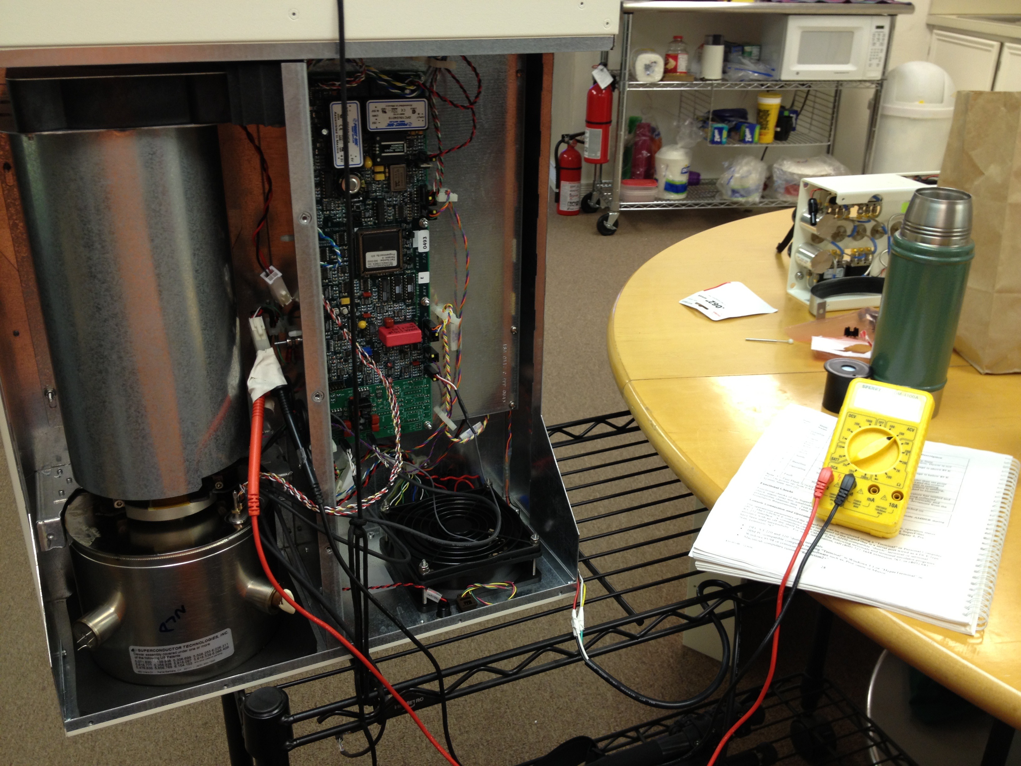
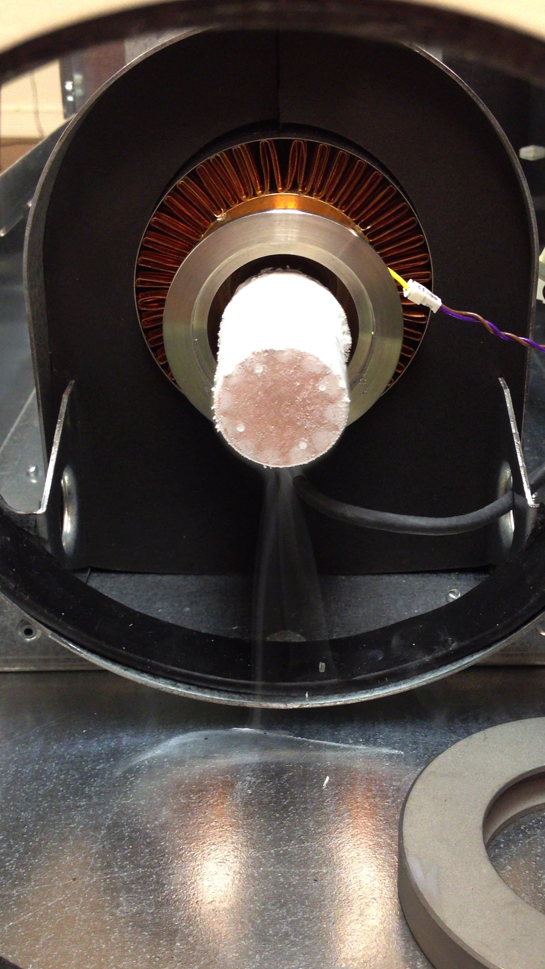
The cryocooler is mine and it is used to cool superconductors in RF filters. It is essentially a AC driven sterling engine running in reverse. Instead of heat making motion, we make a reduction in heat with motion. BUT I use it to liquify air. So fun!
Do you know where I might locate a needle valve, relief valve and rubber bung?
It would be interesting to put the cold end of your cryocooler in a vacuum chamber, pump down the pressure with a roughing pump, then see what happens after a day or so with your cryocooler running. I bet you could get a decent vacuum in a small chamber with that setup.
I don’t have any of that stuff at the moment.
The cryocooler has it’s own dewar but it’s very small and the power supply and controller very big. 
Does get down below -350 F
From my research for the HAB project, general silicone caulk is water resistant, but not a vapor seal. If it turns out that it isn’t good enough I would suggest an epoxy. If you need something elastic then here is the best choice (but expensive):
http://www.2spi.com/catalog/vac/vacleak.shtml
-Robert
Thanks, Robert. Others who have home-built a nitrogen laser have used clear silicone sealant or epoxy cement. Silicone is sufficient, as the vacuum and gas fill requirements are modest, and has the advantage that it can be removed easily for disassembly.
http://www.jonslasers.com/my-first-nitrogen-laser
I don’t know much about the sealant you referenced, but it looks like it would be used in a system that’s already fairly well-sealed.
One piece that I’ve overlooked is that we need to shield the spark gap. It produces a lot of UV light and it’s noisy. I haven’t thought of what we might use as a shield around it, yet.
There is some thin aluminum sheet in the scrap metal bin behind the HAAS that would work well.
I think that would short the spark gap. It’s running at >9kV.
You need an air gap between the conductive shielding and the spark gap of about 1" for each 15,000-30,000V of electrical potential.
But sparkgaps put out a lot of electrical noise and need a conductive metal shield to keep that noise from interfering with other devices/users.
Complicating the matter, the spark gap is attached to the copper plates of our capacitor. It doesn’t have an inch of clearance.
Then you need to find another way to electrically shield the spark with some form of faraday cage.
To give you an idea of just how much noise a spark gap can emit, the original marconi radios used a spark gap not much different from yours to transmit signals across the atlantic. And they did so using a large bandwidth of the electrical spectrum.
Here’s a diagram of what we are assembling:
Looks like the entire device may need a grounded metal case, with only a small window opening for the laser to emit.
Walter & Richard,
I beg to differ.
Looks like the entire device may need a grounded metal case, with only a small window opening for the laser to emit.
Use an upside metal paint can with an insulated standoff over the spark gap and have a removable lid so you can observe the spark through UV safety glasses.
The copper on the bottom under the spark gap should be sufficient to shield on the bottom side or at the worst put everything on top of a thick plywood sheet with an aluminum sheet underneath.
Should be good enough for UV and RF protection, though I think this is overkill as we are not talking about an arc welder.
And BTW, we do run arc welders in the metal shop and no one seems to complain about equipment interference.
JAG “Nerf Ball High Voltage Safety” MAN