Would anyone be available to teach / show me how to use the lathe tomorrow (wed july 8th) anytime after 8pm?
I have a 3/4" x 12" steel shaft(the intermediate shaft for gokart project), I need to cut it in half, and then center drill both ends, one end slightly more than 10mm, the other with an R drillbit to tap by hand for an m10x1.5 bolt. The only lathe experience I have are the few youtube videos I just watched (I really should have attended the steam engine build classes)
I don’t think I’ll be there tomorrow night. I’ll be there from around 10am-1pm, if you could come up then.
I’d suggest that you cut the shaft in half on the horizontal band saw, rather than trying to part it on the lathe. You can leave it a little long so you can face the ends
I can be there this evening to help. Let me know if you want to meet me there this evening.
1 Like
Thank you for the help, was able to get the shaft machined perfectly, for a follow up question, would it be possible to face an abs plastic collar that is around the steel shaft? Would some combination of tool and speed actually cut the plastic instead of just gumming up?
The problem is the 3d printer was apparently out of calibration, so the bottom of the coupler part(which is what mates to the motor hub) is not perpendicular to the shaft. Would there be another method to mill the plastic part to make the face perpendicular to the shaft that is running through it?
https://lh6.googleusercontent.com/-v2mSPCfZRyA/VZ4tIsSnDnI/AAAAAAAAfeU/aNhk8y8ksNQ/w958-h709-no/IMG_20150709_031313.jpg

It is possible to turn ABS. If we have inserts for plastic, then use those, but if we don’t use the turning inserts for Aluminum. Those should work passably well.
You want high speed and high feeds when cutting plastic. All that said, I suggest you best bet would be to re-print the part on a different printer.
I would expect the 3D print to just come apart when you tried to turn it. I think you’d have better luck buying a piece of Delrin and making the part from scratch. The only difficult part, from what I can see, would be the keyway. Or, you could calibrate the 3D printer & make another one.
1 Like
This is certainly a possibility, particularly if the print was made with a lot of ‘space’ on the inside. Since this was to be a mechanical part in the go-kart power transmission I assumed that it was nearly a 100% filled part. Which would make turning it doable.
I have turned PLA printed parts on my Sherline, with a lathe bit ground for plastic and it worked fine. Albeit it was really ‘messy’ with all of the plastic chips that piled up. Just needs light cuts with high speeds and feeds.
However, if the part has a lot of ‘space’ in the interior it will not turn well at all.
That said, I would try reprinting before I tried turning the part. Less work. For the actual part, I would suggest talking to John about developing a model print of this for casting in metal. Something most space’s would be able to accomplish and this piece really should be metal. Barring that it should be relatively easy to machine as Bryan said. Just expect to have a key slot instead of a built in key.
You can pick up an asian broach set to fit this keyway for about $40-$50.
1 Like
I printed it at 100% infill, but yeah it could still just start delaminating at each printed layer. I might try turning it while I wait for another print since I already have 2 messed up ones anyway (~takes an hour to print)
1 Like
I wonder if what you are seeing in the 3D print is not a miscalibration, but rather warping of the print. At 100% fill, I think it is more likely warping, but the 3D print gurus could say better.
You may want to print with a large brim, say 10-15mm. This could help reduce warping in the base layers.
The lathe worked great on the plastic, far righy turned out to have much less skew, but I would probably still want to face it on the lathe to make it perfectly flat

1 Like
Cool. What’s that you have it mounted on?
1 Like
It’s press fit on the 3/4" steel shaft with a keyway that the gokart sprocket will be mounted on, I probably should have left more of the plastic coupler hanging off so I didn’t have to be as careful to not hit the steel with the tool at the high speed.
1 Like
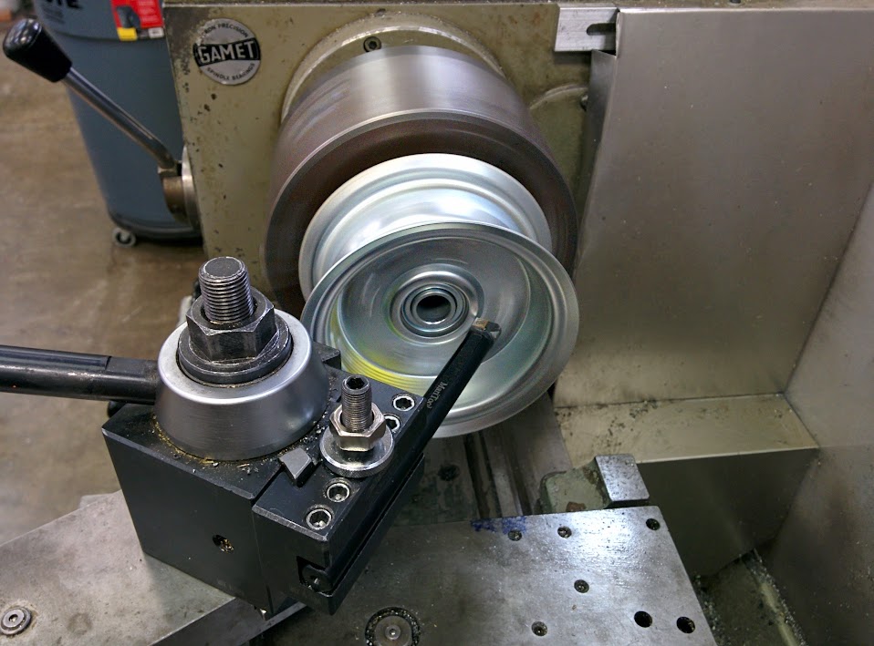
For another lathe question, we have wheels that look like these, they are split rim made of what looks like stamped sheet metal. One side has a bearing and hub pressed into it, the other has an inner lip
http://www.northerntool.com/shop/tools/product_200356965_200356965
And I need to bore out the hole in the center of them, so they end up looking like what this person did:

As described on this build page The Legendary Saga of Chibi-Mikuvan Engineering, from October Until Now – Equals Zero where he says “I had to carve off the existing bearing hubs from the Harbor Freight wheels. I chucked this into hugelathe and ran a standard boring bar into it, boring away at the face of the wheel until it flew off.”
Would our lathe be capable of holding the ~4.25" diameter half of a wheel rim directly by the outter lip? Or would I need to make something that mounts to at least 2 of the existing holes before trying to put it on the lathe?
The goal would be to get clean wheel halfs as pictured above by the other builder, then 3d print the following template, then drill out the red holes to bolt these wheels to our nice aluminum wheel hubs (which are 3 holes on 2.5" diameter vs current 4 holes on 2.75" diameter)

I think I realize a good way to hold the wheel rim in the lathe, by just bolting the two halves together and cutting both at once, with the bearing/hub to remove in the lathe chuck (the small cylinders in example picture above from other site). Is there a specific tool that would be good to make a narrow plunge cut into ~1/16" thick steel?
The 4 jaw should be able to hold a 4¼" object, if it’s sturdy enough to be gripped without distorting. I don’t understand your question about plunging into steel.
But in general I think it’s best to do all of this on the Bridgeport. Enlarge the center with the boring head, and then move to the X/Y coordinates of the 3 holes and drill them.
1 Like
Here is what I ended up doing, which seemed to take a really long time, any suggestions on if this was the best approach?
The initial hubs:
https://lh6.googleusercontent.com/-bd5KAtSdmac/VaLq0oa5uQI/AAAAAAAAfos/SZ6V3kCPUSA/w958-h709-no/IMG_20150712_173133.jpg
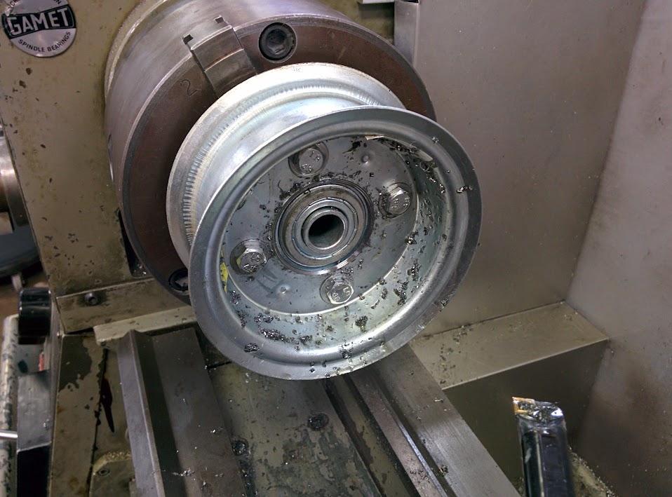
I mounted it in the lathe and used the small boring bar, having to avoid both the bolts holding the two halves together and the bearing from the original hub made it very difficult to get a good angle, and the hubs are really crappy and wobble, which helped lead to my murdering of several tool inserts.
But I did get through both sides eventually and the outter rim detached
Then I found some scrap aluminum and centered the DRO on the bridgeport and drilled the 4 bolt hole pattern (holes are on a 2.75" diameter circle)
https://lh4.googleusercontent.com/-QnkEDh80MKo/VaM0VRR-xII/AAAAAAAAfp8/1GkVBiOljcc/w958-h709-no/IMG_20150712_224506.jpg
Bolting half a wheel at a time I then drilled the 3 hole pattern


It has some wobble, but I think it had that wobble in the rim itself from the factory, not sure what kind of balance you can expect from a $5 wheel and tire
2 Likes
