I’m looking to build a coilgun. I’m planning to run it at high voltage (~550V), high current for short pulses (no estimates yet, on the order of milliseconds). As such, I picked a very large and reasonably cheap IGBT to drive individual sections (datasheet). This will have to handle both closing and opening at voltage.
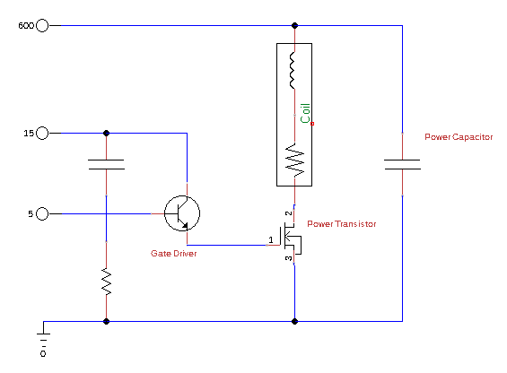
I learned recently that gate drivers are used to control power transistors, for better switching performance and reduced power dissipation in transition. I have a basic circuit diagram where a gate driver closes the power transistor, and the emitter drains directly to ground. Do I need another gate driver to open it? Or can ground absorb the gate charge fast enough to prevent damage? If the answer is “it depends” what do I look at to decide?
Thanks in advance for any advice!
You can calculate the turn off time. It’s basically an RC - gate charge is the C and the gate leakage, which they unfortunately they do not provide. Modern IGBTs are really good, so low nanoamps or picoamps. You’ll want a turn off transistor. I’d look at a dedicated gate driver IC.
A bigger problem will occur when you turn off current to the coil. It will ‘flyback’ - it’s voltage will increase trying to keep the current constant. Unless you have something in the circuit to protect it, your transistor will breakdown and proved the path to discharge the inductor.
You can prevent this with a diode of appropriate voltage and current rating across the coil in the reverse direction. When the coil flys back, the diode will provide a path for the current limiting the added voltage to the diode forward voltage drop.
I don’t know what the resulting magnetic effect is going to do to your coil-gun as it will extend the magnetic drive pulse.
Ah, thanks, forgot to include flyback protection. As for the effect on timing, it means there’s a ramp-down period after signal turn-off; I’ll have to account for this when I tune the coil. (Or just turn off early and hope for the best.)
I was considering using the flyback to recharge the power capacitor bank using an H-bridge, but that’s (a) expensive and (b) finicky so I’ll save it for later iterations.
So a turn-off transistor simply bypasses the gate leakage. That simplifies things, I don’t have to raise the emitter voltage or add -15V power supply. I’ve heard advice to drain the gate into a (much) larger capacitor, so I’ll look into it. Thanks!
I’d look at switching supply drive circuitry for examples.
I think there is a trick you can do with a rectifier bridge to recharge the cap, but it’s not a huge efficiency increase. as you still need to reset the coil core to zero or you end up saturating the inductor.
Some while back the mag Nuts & Volts did a diy single stage coil gun. They used an SCR to dump the cap bank into the coil. Might have some ideas for your project
Out of curiosity - did a search using “coil gun multi stage”. Interesting stuff out there.
Wether or not you need a negative voltage for turn off will depend on how quickly the IGBT turns off and the Cgc (miller capacitance) of the device. As the device turns off, Vce increases and that dV/dt will push charge through the miller capacitance into the gate. If the drive circuit can’t pull that charge out of the gate in time, it could turn the device partially on, burning it up, or overcharge the gate, also destroying the device.
In small, slow devices, driving the gate to ground through the gate resistance is sufficient. As you get larger or faster a negative drive voltage can be added to help sink more current, then if that’s not sufficient a driver with an active miller clamp can be used to bypass the gate resistance and connect the gate directly to the emitter. Where your design falls on this spectrum is hard to say without more analysis.
I think you should jump up to a 1200v device, with a 550v DC link. There’s usually very little margin built in to Vce_max spec (our 1200v devices sustain about 1250v in avalanche), and it’s definitely not ideal in the long term to use your power devices as clamps. At high switching speeds, wiring inductance and the esl of dc capacitors can cause surprisingly significant overshoot. In my experience devices are usually only run at nominal voltages <80% of their max rating.
