
Hello MakerSpace Electronics,
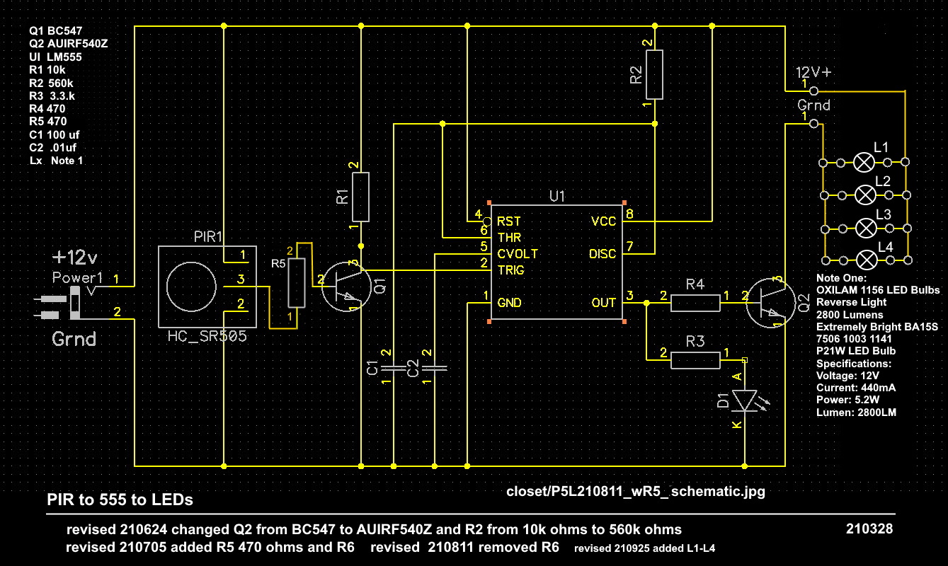
Have developed a circuit, PCB and 3D-printed object that turns
on four 12 volt LED lights when activated by a PIR sensor that
controls the on-time of a 555 timer in monostable mode.
This is the schematic
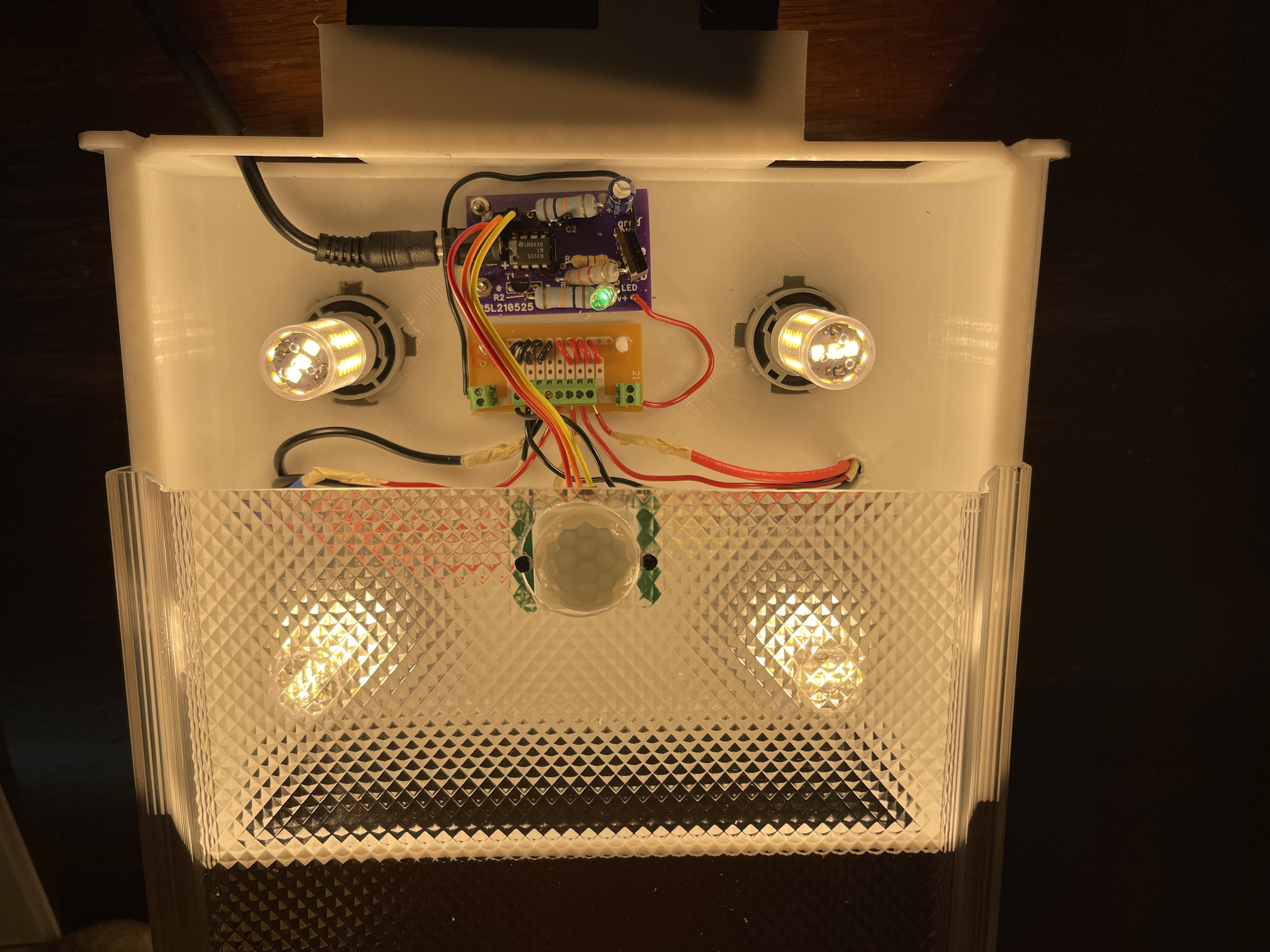
This a picture of the fixture with the lens slid back partially
so the inside electronics can be seen.
After designing the schematic, breadboarding the schematic, desigining the
PCB and having the PCB manufactured, desigining the fixture in 3D, having
the fixture 3D printed and assembling all the parts I ran the fixture
for about an hour in my office (had tested the system for about thirty
minutes on the bench) and I looked over and there was smoke coming off the
fixture.
Not sure what blew. By the time I could get the power turned off it was hard tell
visually which component fried but it seemed like Q2 was warmer than anything else.
Thought I had solved the hyper current issue.Originally, a signal transistor, a BC547, was used at Q2.
It got hot and so the BC547 for Q2 was replaced with a AUIRF540Z.
Did not seem to have heat problem with Q2. The data sheet
https://www.mouser.com/datasheet/2/196/Infineon_AUIRF540Z_DS_v01_02_EN-1731032.pdf
indicates (I think) that the transistor is good to 36 amps.
This is a URL to the 12 volt lights used in the fixture
So trying to figure out
- Why the circuit smoked?
- If the problem is Q2, the AUIRF540Z, why did it overheat?
Any insight would be greatly appreciated.
Thanks.
Allen Pitts, Dallas Texas
[email protected]
469 713 4147