You don't need an Arduino to Flash an LED

Continuing the discussion from A SMD hand soldering class:

This class is now on the calendar for the 24th of this month.
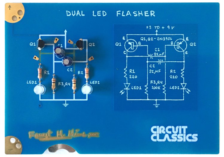
In preparing the materials for this class, I have been ‘characterizing’ the circuit. This is one of the techniques we will be discussing during the class. In this case I used four different values for the resistors R3, and R4, and 12 different values for C1 and C2. This allows one to determine the flash characteristic of the circuit over a wide range of component values.

It also lets you produce cool diagrams like the one below, which make it easy for someone just learning to be able to select the best combination of components to get the circuit to behave like they want.

Class Link: https://calendar.dallasmakerspace.org/events/view/2988

5 Likes

Because 1e+01 is so readable to a beginner…

1 Like

Raymond, I know you like to be an ass… but the above is my first draft and not what I will end up using in the class. I believe if you ask around my classes are well thought of. I spend a lot of time preparing for them,

That said, if you are going to attempt to create a graph like the above (characterize a circuit, you will need a high school level of algebra and be used to dealing with things like log regressions… In other words, creating the graph and the technique are not ‘beginner’ techniques; however, using them is. Including reading scientific notation, since that is common in the datasheets people are going to need to use.

10^-1, 10^3, etc are no different from 2^1, 2^4, which are also basic math needed to understand binary numbers. Something beginners do need to learn…

I know you like to lawyerize and complicate things - oh, and hold grudges and call names. Items like that on a graph can scare off beginners. Please make it simpler for them.

Good grief…just jump into the deep end of the pool. We’ll throw you rope if needed.

3 Likes

So, I have been continuing on preparing class material and made a slightly modified version of the circui that will help explain how it works. I inserted a pair of LEDs, installed in opposite direction, Between the capacitor and collector of the transistors. The green LEDs show when current is flowing (+ to -) from the transistor collector to the capacitor, while the yellow LEDs will flash when the current reverse and flows from the capacitor to the collector of the transistor.

I am hoping that video of this in operation (while the students can handle the actual circuit) on one side with a display of the Oscilliscope waveforms on the other side will help the students understand the operation of the circuit.

2 Likes