I’m assuming 3pm sunday is still a good time to meet tomorrow.
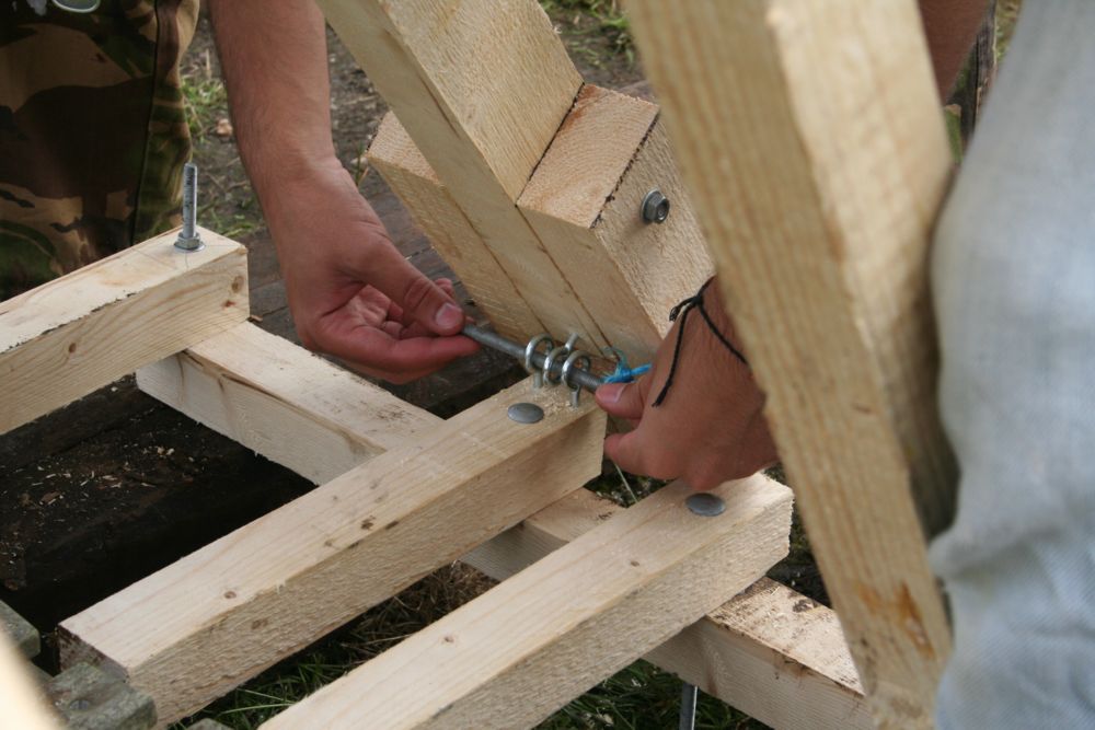
We need to iterate on the prototype to get it firing reliably (better weight axle mount, decrease weight fall gap, actual sling) so that we can experiment with different arm and sling lengths.
When we were kids, my brothers and I would go around singing, “Secret Asian Man.”
2 Likes
I am going to busy helping to hang up 10x10 exhibits.
I’ll be at the space making stuff, and should have time for 3pm meeting.
I have a class at 5 to teach tho, but sounds like we are on a roll after building the 2x4 prototype. They really do help
Made some improvements and it now fires a grapefruit sized object (.4 kg) ~150 feet. Replaced the weight holding axle with 1/2" iron pipe (was 1"), decreased the width of drop slot, reinforced and aligned rails, used some 1/8" steel bar stock to make plates to aid in axle to arm mounting, new sling, added 3rd wheel inside rail to allow weights to be raised higher.
Precision wood working

Also the wheels being used are from casters and so they had a curve to the top, flattened them out on the lathe

Glow stick + wall wart transformer make a good night time test projectile

Video of test fire:
Next we need to start experimenting with different variables to get some data before starting the full scale build, things like projectile weight by filling water balloons to different sizes, sling length, hook angle, arm length, arm to pivot ratio, etc
3 Likes
Anyone have any electric solenoids they could donate to this project? Or any ideas on a good trigger? Need something better than the 2x4s in video which takes two people to arm, the requirements would be:
- As weight bar is raised, it must automatically latch and secure the bar (so that a single person can load and arm it)
- There needs to be a mechanism on each of the uprights holding each side of the bar(to avoid twisting arm, and dont want a string on the end of the arm because then the arm is under tension from the weights)
- Each side needs to release near simultaneously
Initial idea:

The question with initial idea is how to pull out the pin that would be holding the arm up, using bicycle cable and spring could work, but mounting two solenoids seems easier
The latch/trigger on a Trebuchet is subject to a LOT of force. I suggest you’ll adhere to the KISS principal.
For this scale each latch will just need to hold ~5 pounds (the ratio of pivot to arm to latch means most of load will be held by the pivot point that is closer to the bar), these car power door lock actuators seem too cheap to not try
Why do something at model scale you will not be able to replicate on the full scale? KISS principal.
1 Like
We plan on taking the scale model to sling fest along with the full size beauty so that the kids have something to shoot. Safety latches are a must! (As much as my son wants to take a ride on a trebuchet)
From the video it looked like it’s firing at a fairly low angle. You’ll get the farthest distance with a 45 degree launch angle.

1 Like
I attempted to calculate the strain on full size main axle, I realized it would require some kind of advanced simulation to actualy produce a formula that gives angle of arm over time, so instead I just analyzed the slow motion video frames to get position over time of the weight, it’s very rough since I was just eyeballing the pixel location of the weight in each frame. This data covers approximately a 0.5 second range (which is what you would expect for something freefalling from near 4 feet)

Red is position, blue is velocity, it seems like it could be approximated by saying its accelerating at 1g 66% of the time, then decelerating at 4g the remaining time.
In the full scale that means the 500 pounds of weight on each side would be exerting a force of 2,000 pounds on the rod
I used the following two sites to get the formula to calculate the stress generated on the rod
For a 2 inch diameter rod the stress would be (2000 pounds * 12 inches) / (0.784 in^3) = 30,612 psi
For a 2.25 inch diameter rod the stress would be (2000 pounds * 12 inches ) / 1.11628 in^3 = 21,499 psi
It would probably be good to have a safety factor of at least 2, especially considering I have no idea if these numbers are plausible.
- A second order PDE could be formulated to determine acceleration, etc
- The force/stress could probably be determined from an energy balance equation
- Look up an S-N diagram to determine what the maximum stress for the (approximately) desired endurance limit will be (low cycle fatigue).
- For the trigger, I believe skydiving parachutes have some sort of cascade which reduces the amount of force required for release
It would be really nice to have a passive spring loaded latch that locks itself automatically when the bar is raised, instead of having to manually set the trigger each time. If a manual trigger setup is used something like a snap shackle or seacatch would be an option
1 Like
Here’s a web site with some stuff on it.
http://www.siege-engine.com/TriggersAndCatches.shtml
I like the idea of a variant on their “opposing tooth wheel” trigger.
I think it might work well, and do what you want, to make the trigger bar spring loaded, with a notch in the wheel, and rotation limitations such that as the bar is raised, it engages the notch on the wheel. Once in RTF position, the trigger bar “clicks” into place, locking it all. When released, it rotates down to “unloaded” position, awaiting the return of its weight bar buddy.
Another page with some stuff on it.
http://members.iinet.net.au/~rmine/triggers.html
I thought this one looked interesting.
http://members.iinet.net.au/~rmine/pics/trigger/cocky.gif
I also thought this idea, of using a door latch, was a good one:
And there’s always the old 3-eyebolts and a rod idea:
Here is my idea for the full scale trigger drawn out, it would be plasma cut out of 1/4 or 3/8 steel plate. Either a rope or the door lock actuator would pull on the open hole to release the latch

Me and few friends built a trebuchet for a school project years ago, and while it was a more conventional style, that used the 3 ring with a pull pin type release, which did work fine but it took quite a bit of force to pull it. Granted, we had ~2000lbs, or maybe a little more, of counterweight to throw a 12lb bowling ball, so just a wee bit o’ force on that release pin…
While simplicity is great, I am liking some of the ideas for an improved style of release.
1 Like
Here is a possible steel design, bill of materials would be around 800-900, (would be interesting to do something different than wood, and it is still within budget). Any thoughts on how this looks?


All of the supporting braces are 1.5"x1.5" 1/8 steel angle, drawn here as square tube for drafting simplicity, the legs sticking out would bolt on, to move it around it would be rotated over 45 degrees and wheels would be mounted on the braces going from base to end of rail. The base would weight around 400 pounds.
The largest structural concern is that other than below about 1.5 feet from base and at the ends of the rails nothing is connecting the two sides (anywhere arm swings through = must be open), which is why I left the uprights as 4"x4" 11ga (same material as legs on auto table, except each one would be 8.5 feet tall)
I scheduled a meeting for this sunday at 3pm as a design review / planning meeting, @mreynolds let me know if a different time would be better and I can move it.
We have roughly 6 weeks before the competition on October 30th
2 Likes