Laser Etching Painted Plastic

Hi there,

First of all hello from MADE makerspace in Barcelona!

I know that this is quite old topic, but it’s one of the few resource I was able to find on this subject online.
I’m trying to achieve an exact effect and it’s also for an flight sim (Cessna Citation Mustang). We have an Universal ULS25E laser engraver (20W) which is almost 20 years old but works like a charm!

I have a question to you. I’m able to to get an beautiful finish using your technique. I’m applying 1 layer of transparent plastic primer, 6 layers of white acrylic paint, 3 layers of acrylic matte varnish, and on top 3 layers of black acrylic paint. All paints are in spray cans. I get a very nice finish after engraving and I’m able to remove only the black paint to reveal the white paint…but the paint looks yellowish and burnt when backlit! It looks great when not lit, but with the backlight on - it’s bad.

Do you have any solution for this? Maybe I should try with a different white paint as it’s most likely this paint that gets burned?

Cheers,
Bartosz Szymanski

1 Like

Bartosz,

I think part of your problem is the 6 layers of White plus all the matte finish. I too have noticed that there is some yellowish appearance to some of the back lit panels I’ve built; although not to the degree I think you have. As you are finding out, the key to getting professional results is the painting in both thickness, consistency and light transmission. I’ve been told by a shop that makes some of these panels for professional flight simulators that they use 2 layers of white and 1 layer of clear before they add the black. This means the settings of the laser power and speed are critical so as to just take off the black and not burn through the white. Additionally, the pros mix up their paint and use a professional paint sprayer to make absolutely sure that the paint thickness is consistent. It’s hard to do that with spray can paints. The other advantage that the Pro’s have is that they use special light measurement instruments to check the illumination of the panel before painting it black.

In a darkened room they use some sort of spot measurement tool that can test the lumens, wavelength and consistency of the illuminated panel. To do that they install the back-lights into the panel after it has been painted white front and back (leaving only the light bulb/LED pockets unpainted), power up the back-light lamps and turn out the lights in the room and take measurements with their fancy measurement tool. If the white output is too low to meet MIL-SPECs (MIL-P-7788-F requires 2.0 footlamberts +/- 1.0 footlamberts) or if the color wavelength is not Aviation White (see chart below with Aviation White range in blue), they discard the panel.

If they see that there are hot-spots causing illumination to not be consistent across the panel, they use an air-brush to add a bit more white paint in spots to even out the illumination. Obviously, these tools and procedures are probably beyond the abilities and budget of the hobbyist.

Here’s a picture of one of my panels which I think come out pretty well for a hobbyist.


In this case I use 2 Layers of White Krylon 2X Painters Choice (not sure it is available in EU), followed by 2 Layer of Matte Krylon 2X Painters Choice. (The 2X paint is thicker than standard spray paint.) It may be that I too need to switch to thinner paint layers of white. That is on my ToDo list.


Here you can see the back of this panel with the screw inserts (install with soldering iron to melt into plastic) and the DIY .005" Brass Heat Sinks. (This was before I learned that I needed to paint the back white too. I had to go plug the holes and cover the screw inserts and add the white paint after the fact.) The trick painting the back is to plug the light pockets (where you see the Heat Sinks) to keep paint out. You also should bead blast the plastic with the very fine glass beads before you paint it for better light diffusion. (Another trick of the pros.) This means that the light from the bulbs go into the acrylic via the walls of the lamp pockets and bounces around inside the plastic due to the white paint covering the entire panel except the lamp pockets.

Finally, the real military panels use a 7152 incandescent bulb (hence the need for the heat sink) with a Lunar blue filter that fits over the bulb and into the pockets that you see and shifts the warm incandescent light back to a cooler white. (Or with the newer panels, a green NVIS filter is used to shift towards Green light.) The problem is that these filters are about $5 USD each and you have to buy a minimum order of 100!!! Again, that’s probably beyond what the hobbyist wants to spend. (You might try painting the walls of the pockets with a thin, thin coat of blue acrylic paint to try to get the same effect without spending the big $$$ for filters.) If you are using LED’s for illumination, you might try different color wavelengths of LED to see if you can achieve a more white appearance.

So I suggest you keep experimenting with your painting (don’t forget to paint front and back) and reduce the number of layers of white and matte (which means reduced laser power and speed when engraving) to improve the light transmission qualities of the white/matte layers to reduce this yellow appearance. It is truly a “trial and error” process. I’ve had many, many attempts at this before I got to what you see in the pictures. Keep in mind that the pros have had to experiment with paint until they achieved the requirements of MIL-SPEC’s and that is why they won’t tell us more about the paint that they use. It’s only from former employees and others that I’ve been able to slowly glean the above information.

In the end, you may have to settle for hobbyist quality and just live with some slight yellowish tint. However, I’ll bet you can get pretty close to the pros by following some of the above advice.

Good luck.

Beau

8 Likes

Beau - what an awesome, thoughtful response. You are a hero!

4 Likes

John,

It’s just one of the more unadvertised advantages of being a Makerspace member. Access to knowledge of others and their willingness to share and help.

Cheers.

Beau

7 Likes

Just as a curiosity, can you get the same effect by using one layer of light blue Krylon (don’t know if there is such a thing) as a replacement for one of the white layers? That’s a trick that dye-sublimators and decal artists use because there is no white printer ink - the eye sees the light blue and the brain thinks it’s white.

Possibly.

However, I think it would be easier to paint the walls of the lamp pockets blue. You can then make adjustments to the effect by adding or removing/thinning the blue paint in the pockets until you achieve the desired results.

Doing it your way you have to get the Blue layer “perfect” and I would think that would take lots of trial and error.

Wow, Beau that’s an amazing response! Thank you so much for your time! :slight_smile:

I’m using very similar technique with the panels making. I also use the brass inserts. I cnc mill the panel instead of laser cutting so I can mill the pockets for the inserts and LEDs. My plan is to use the same technique as in this video: https://www.youtube.com/watch?v=vf7tQNYqliw

So first cnc mill the panel. Paint it white, paint it black and then back to the cnc mill to remove only the paint (0.1mm or less) from the LED pockets. Off course laser engrave the labels.

But back on the subject. I think the secret might be in the type of paint used. I have a friend who has a friend (I know…) who also works for a aviation panels maker. He said that the paint they use comes in an unlabeled cans so the workers can’t know what it is :smiley: He says that it smells like acrylic, that’s the only thing he can tell…
So probably it’s some kind of heat resistant paint. I just bought an white heat resistant paint that is used for painting fireplaces, exhausts etc. Let’s see how it will work. The only downside is that it’s not that perfectly white like an acrylic paint…

I will keep you posted with my progress!

p.s.
One of the techniques to avoid the burning residue during the engraving is using the masking tape. Just stick it on top of the panel and engrave trough the masking tape and paint. The residue will stay on the masking tape. Works perfectly. Although I noticed that when you engrave with a low power you usually don’t get the residue.

Cheers,
Bartek

Bartek,

Thanks for the link to the video.

All of this discussion prompted me to do a bit more research into color and chromaticity. I found the following YouTube videos to be quite helpful in understanding some of this, especial the 3 “Color Vision” videos by the Ophthalmologist. (There are more than the 3 if you find the topic really interesting as I did since I have some R-G Color Deficiencies in my vision.)

The Chromaticity Diagram

Color Vision 1: Color Basics
Color Vision 2: Color Matching
Color Vision 3: Color Map

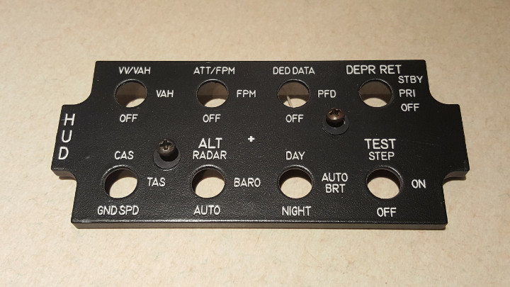
As for the paint used by the Pro’s, I can tell you that MIL-P-7788F “Panels, Information, Integrally Illuminated” (you should get a copy of this) calls for FED-STD-595 colors of:

  • Black 37038
  • Gray 36231
  • White 37875 or 37925
  • Yellow 33538

You may be able to get a paint shop to mix some Acrylic paint (yes I too think that is what they use) to match those colors. However, I suspect that there may be variations in the light transmission qualities of different paints that meet the above colors that may result in a difference in the reflected color when illuminated by a spectrally pure white light from the front, versus the color seen when the paint is illuminated from the back by the same light. Basically, what I’m saying is that the wavelengths absorbed by the paint may differ for reflected light versus transmitted light. Getting a paint that doesn’t have a significant difference between reflected and transmitted chromaticity may be why the actual paint they used is kept “Top Secret” by the Pros.

Also, I think I quoted the wrong chart in my last post. I think this is the correct graph which shows what they call the type (1h) Lunar White range.


You can see that this range includes the “E” equal energy “White” point of x=.33, y=.33 discussed in some of those videos. Unfortunately, this comes from the old MIL-C-25050A document and it has been superseded by SAE AS25050 document which is copyrighted and costs $76 to download from SAE so I don’t have the latest info there. Still I think the old spec is close enough for us.

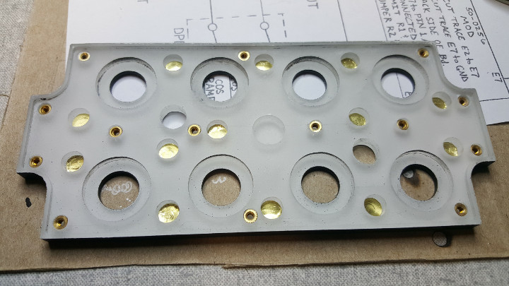
As for removing the paint by milling, I’d like to know more details on how you are doing that. It seems to me to be pretty difficult to jig up the panel so that it is perfectly aligned and centered so that the milling process just takes of .1mm inside the pockets. (That’s only .004" to us non-metric types. Yikes!)

You’ll notice in the video that they are using a special electronic measurement tool on their CNC that accurately probes the panel to determine the exact X,Y,Z center of the material. I guess one can do that manually but to .1mm (.004") accuracy???

They also have an expensive machinists vise that has been mounted and calibrated to be perfectly flat to the mill. This makes it difficult for the hobbyist to accomplish in my opinion so I’ll be interested in more details on how you do this yourself using hobbyist milling equipment. (Or maybe you’re using a high-dollar mill at your Makerspace to do this. I’m doing my milling in my home shop using a NextWave Automation CNC Shark Pro HD1 so it’s hard for me to achieve this sort of accuracy with just a $4000 CNC.)

In my case, I’m using circular lamp pockets which are easy to plug while painting thereby avoiding milling off the paint. However, if you are using the “race-track” pockets, finding a plug for those pockets is more difficult. (Although you probably could machine a set.)

Also, I don’t think you need to go the heat resistant paint route. I doubt you are getting any heat related yellowing of the paint here. I think the heat sink prevents heat damage and if you are using LED’s, I doubt they produce enough heat to worry about but I could be wrong. Additionally, I’ll bet that the additives to make the paint heat resistant will affect the chromaticity of the transmitted light making it more trouble than it is worth.

Finally, here’s another tip from the pro’s: clean off the residue with 409, Castrol Super Clean or Simple Green. (Not sure you guys have those products in the EU but I’m sure you have something similar.) Using masking tape only makes getting the laser speed/power just right more difficult in my opinion. 409, Simple Green or Castrol Super Clean is what I’ve been using on all my dials and panels and it works nicely. BTW, once the panel is finished, I give it a few coats of Krylon Matte spray to protect it. I’ve been told some of the pros use Polyurethane with a flattening agent as the final protective coat.

P.S. I misspoke in my previous post. It is “Rustoleum” 2x Painters Choice paint, not “Krylon”.

1 Like

Beau,

I see that you approach the problem in a very scientific way. I like it :slight_smile:
I didn’t know about the possible difference in the color when using reflected light vs transmitted light. Interesting. It might be an issue in deed. I like those charts and I’ve seen the MIL-P-7788F before. The firend I mentioned before send it to me and he said that it’s like a bible for them…but I’m not sure if it’s very helpful for us. It only stated the requirements that the panels must meet, not how it’s done and with what type of materials.
In my case I still think that the paint gets burned a little bit.

What do you say about making an simple test. Test the backlit color after painting white but before painting black. Basically do what the PROs are doing but without a sophisticated measuring equipment. In our case not to test the light distribution, but just to check if the color is white or yellowish. If it’s white, then it gets yellow during engraving. Otherwise it’s the difference between transmitted and reflected light.
I will give it a try tomorrow.

Today I painted two pieces of transparent perspex using different white paints. For the first one I used dissolvent based white spray paint and for other the mentioned heat resistant paint. In both cases I applied 4 coats of white, 2 coats of transparent and 3 black. I will engrave it tomorrow when it will be fully dry and I will let you know how it turns out.
Btw. with the heat resistant paint the idea is to avoid paint burning during engraving. It’s not for the overheating of LEDs. That’s not an issue. Even regular acrylic paint is usually certified to withstand up to 100-120°C and I think that acrylic (perspex) starts to melt at 160°C. I measured the temperatures of SMD leds on my backlight PCBs when fully backlit and it’s usually around 45-50°C max.

Regarding the CNC. I haven’t tried this method yet, but I milled parts before that required flipping and high precision and it wasn’t very difficult to align it so this shouldn’t be a problem. You can always mill the pockets smaller so in the second pass after painting you can remove more than 0.1mm to meet your desired dimension. The 0.1mm was just a quick idea, maybe in deed it’s too small. 0.2mm would be better :smile:
We don’t have any fancy high tech CNC at our workshop. Actually we have an crappy Chinese HY3040 5 axis CNC and we use it as a 3 axis anyway as nobody wants to play with 5 axis. When I say it’s crappy, I mean that it’s really not very good. Not rigid at all and almost impossible to square and tram properly so forget about nice face milling finish for example…

Anyway here you can find some of the tricks I use to make it work:

  • If your CNC bed is not completely flat in relation to the spindle, you can mount an MDF board, face mill it to be perfectly flat and then mount your panels to the MDF using double sided tape. It’s a good idea anyway as you can always cut a little bit into the MDF without worrying about destroying your tool. Only sometimes the double sided tape gets caught around the end mill and can affect the quality of the cut. You have to experiment with it.
  • To align the part to be perfectly parallel to the X axis, what I did is I mounted an piece of perspex to my cutting table and then just cut it on the edge with the CNC along the X axis. This way it’s perfectly parallel with the X axis. Later when you need to place an part, you just rest it against this piece of perspex (or other material of your choice).
  • What you saw in the video is a 3D digital probe. It’s used to find the edges of the part with a high precision. I don’t have it. I was considering buying one but our CNC is a typical hobbyist machine and has only ER11 collets and good luck with finding probes that small.
    You can use an old technique instead. Mount an end mill of a known diameter to your spindle. Turn it on on a super slow RPM, just enough to start rotating. Grab an piece of the thinnest paper you can find. Place the piece of paper on the edge of the part on the axis you wish to find the zero for. Very slowly (and I mean very very slowly) jog the spindle towards this edge. At some point the spinning end mill will grab the paper from your hand and this means that the tool is touching the edge (minus the thickness of the paper, but if it’s very thin you can skip this error). When the tool is touching the edge it means that you’re half of the tool diameter off your zero :slight_smile: Repeat for the other axis. For the Z axis it’s the same but you don’t have to subtract anything.

I will keep you posted on my progress.

Cheers,
Bartek

Bartek,

I really don’t think you are experiencing “burning” of the paint. I’m told that the laser doesn’t “burn” it ablates or vaporizes material. The material goes from solid directly to gas. Given that and the fact that you have been using masking tape to avoid the soot from getting on the light plate and not using some sort of cleaner like 409 to remove the soot, what you “may” be seeing is the left over soot in the white lettering. This is why it is critical to use the cleaner to remove the soot to get back to the original white of the paint…

Once you engrave off the black and clean off the soot, your white lettering should look just as white as it did before you put the black (or grey) layers (1 or 2 really thin coats of black or grey maximum) over it. You might also try multiple passes at a lower power setting if you really think the laser power is a problem.

For me, I use Raster Engrave at Speed=50%, Power=20%-30%, DPI=1000 using an Epilog Zing 30Watt laser. That seems to cut through black just fine. In fact, I think those power settings may be a bit too high so I will try lowering them on the next run.

I think you are on the right track by applying all but the black layer and then looking at the reflected vs transmitted light of the panel. However, I highly suggest that you install the Lamps/LED’s and any filters you plan to use in the light plate so you can really see your back-lit lettering color as well as checking for overall consistent light intensity. Again, I think you want to reduce the White and Matte layers as much as possible to eliminate any possible color shift of the transmitted light. I suspect that is where we are running into some slight color shift.

As for the CNC spoil board and alignment, I’m in the process of setting up better spoil boards and machining them flat to the bed for better accuracy. As for finding material center, my CNC can do single steps of .1", .01" and .001". I use this to position a small bit (3/32") to the bottom edge using a .01 feeler gauge, note the Y axis value, repeat for the top edge and do the subtraction for the center value. Then move to the calculated value and reset Y to zero at this point. Repeat for the X axis and I then have the CNC zeroed in X and Y on the material center. For the Z axis, my CNC has an electronic touchplate that is used to detect zero for the Z axis on the top of the material.

I think our discussion has been good but we might want take it offline to avoid boring others with some of these side details; especially on CNC milling. I’ve sent you a PM with my contact info.

Beau

Beau,

You were right about the burning! I engraved the test panels that I painted yesterday and both, the one with the heat resistant paint and the dissolvent based paints are much less yellow than my first try with the acrylic paint. As a matter of fact, they turned out more than acceptable.

I also made an test today with painting two pieces of the transparent perspex with the acrylic white paint and dissolvent based white paint from a different brand. I applied 3 coats and tested the difference between the reflected light color and transmitted light color. The acrylic paint was already a bit yellow from the front (maybe because it was the end of the spray can) but it was super yellow and ugly when backlit! The dissolvent based paint on the other hand was perfectly white from the front and just a little bit yellow when backlit. You can clearly see the difference between the reflected and transmitted light.

I’m now painting another piece of perspex (I have tons of scrape perspex) with the dissolvent based white paint for another engraving test.

I’m not sure if the difference lays in the acrylic paint vs dissolvent based. Maybe it depends on other factors differing between brands as I used two different brands.

When it comes to the engraving power and speed settings, yesterday I noticed that I don’t have to use the masking tape anymore. When I use low power settings I can easily remove only the black paint without generating any residue.
We have an 20W Universal ULS25E and I use it with DPI=1000, speed 100% and 15-20% power depends on the thickness of the black paint. So it’s less power than you’re currently using. You should try increasing the speed with the same power setting and see how it works.

Let’s continue this conversation via email. I will drop you one in a second.

Bartek.

1 Like

Gentlemen, I understand your thought to take it offline, but I really appreciate the detailed discussion you provided here. This is a great learning resource for the other DMS members. Thanks for all the great details!

5 Likes

OK, John. I’m glad to continue the discuss here.

Here’s my response to Bartek minus personal contact info.

Bartek,

Maybe we should take the discussion off-line and move it to email. My personal email is [email protected]. Please send me an email and let’s continue there so we don’t bother folks with our discussion. Even if we are not bothering folks, I would like to have your contact information.

You might also consider joining Viperpits.org. This is the forum of F16 pit builders. While you are not building an F16 sim, (why not???) you may find that F16 sim builders face similar problems as GA Sim builders. My callsign there is “Willy”.

Here’s a video of my buddy flying his sim. (Yes, this is a home built simulator!)

F16 Night Landing, Aviano AB, Italy

The following video is captured from the cockpit by a guy in Belgium while doing a Red Flag mission. It will give you an idea of how realistic the Falcom BMS 4.33 software is. In this video, the guy is not using a realistic sim cockpit but just using the built-in functionality of the software along with a head tracker, joystick, etc.

BMS Red Flag 17-2 Graduation Flight

Finally, I love Barcelona and I spent a great deal of time there doing business when I worked for Frito-Lay/Pepsico Foods International. I hope to go back some day.

I’ll let Bartek re-post his email response to me after he edits out anything in his email he doesn’t want to make public.

3 Likes

Hi I saw your panels and they look really nice. I making some of my own for project. I was wondering though what do you use to solder The lights on two and mount on the backside of the panel?

I machine a .035” recess in the back of the panels and install a .032” PCB with the Lamps soldered to that. The PCB also has a Hoffman connector soldered to it that plugs into the metal back plate.

Here’s one with PCB installed showing the Hoffman connector.

And here’s another set of parts for another panel I built. Engraving was done in Raster mode on the Zing.

I’m still trying to get the White paint mixture/application just right so that it is translucent and all the lettering is illuminated evenly from the back by those tiny lamps. That’s where the Pros make the big bucks as that paint and their process is proprietary.

If you are interested in this sort of thing for Flight Simulators, (in my case for an F16), consider joining Viperpits.org. There is a lot of discussion on making such things there. You can also look at my Build Thread. My CallSign is “Willy”.

Beau

3 Likes

Those look very professional! Where do you get those Hoffman connnectors and which model number do you use?

As for that white paint…we’re both on the same hunt. I saw your question you posted on the German YouTube video simparts.de. I’ve tried several times to contact them…even get an RFQ for making some panels for me…still waiting for their response. Meanwhile a friend of mine is a laser expert with a strong background in materials science. I asked him about this issue. First of all he says to use ONLY acrylic paint, like automotive acrylic…it vaporizes best under the ladder whereas acrylic latex or oil based…they don’t vaporize but rather tend to “boil” and get gooey under the laser energy. He also added that the “special laserpaint” paint is not as “proprietary “ as it might seem…it has to do with the metals content dissolved into the paint: titanium dioxide, aluminum and silver salts. He said there’s a range where the metals content is low enough to allow translucency but high enough to reflect the laser energy, preventing it from vaporizing the paint. He said the hack is reading the MSDS on the various brands of paint paying particular attention to the metal content and the boiling or flash point.temperature. He also said the hack, if I can’t find the so called “special translucent laserpaint”, is to experiment with dpi, speed and power (you seem to have done that quite extensively) the key being to experiment using the gradient feature on the laser and finding the power range where the laser rasters away the black while sparing the white undercoat.

There might be a way of consulting a paint chemist who could have some suggestions as to the ideal range of metals and vaporizing temperatures as well as the ideal mixture we’re trying to achieve.

I’d love to join viperpits…I’m building a sim of the venerable Bell UH-1H helicopter.

Look at the small laser. It has finer controls.

David,

Yes, the paints I have been using are the basic Home-Depot Rust-oleum Acrylic Enamels in White and Flat Black. I’ve been using the Rust-oleum Painters-Touch 2x-Ultra-Cover White to make sure the White layer is thick enough to not be burned through. However, that appears to be too thick for good light transmission. Looks good in daylight but when you back light the panel with those tiny incandescent lamps that don’t put out too much light, it doesn’t look good. Additionally, the rattle-cans do not cover very well and leave spackling that you can’t see until you back light the panel. It appears as a grainy surface when back lit.

My plan is abandon the rattle-can Rustoleum 2x Painters Choice and go to a White Automotive Acrylic Enamel (purchased at English Color locally), to mix and thin it 1:1 (or so) with the appropriate Reducer (Delstar) and then use a 1mm or 1.4mm nozzle on my HVLP spray gun to spray the white layer.

Here’s the text of one of my posts from last November on the ViperPit forum about Light Plates on this topic. (You should join. We have some other folks lurking on the forum doing A10’s, F104’s and I think Helicopters.)

November 09, 2017 (Post in Viper Builders -> Viper Pit Progress Reports -> Willy’s Pit thread)

Yes, I use the Zing for Laser Engraving those panels. The big machines are really too powerful. Typically I use Raster mode, 1000DPI and somewhere between 30% - 50% power at 50% speed. Of course your mileage may vary greatly depending on what Black paint you used and how thick it is. You will probably have to experiment with your paints to find the happy settings.

BTW, I forgot to mention that after the Zing has set unused for a bit, it’s power output is not at full power. Before doing your engraving, you should probably always run a vector job at 100% power on some scrap material to “warm” up the laser. Unfortunately Epilog Tech Support can’t seem to tell us how long that job needs to run to bring power back up. They say it depends on how long it has been sitting unused.

Happy Lasering folks.

I’m wondering if possibly adding additional titanium dioxide powder to the paint would help improve the reflectivity against the laser or even some additional aluminum and silver powders before spraying