Repairing a self-balancing electric unicycle

Hey everyone, a buddy of mine ordered an IPS electric unicycle. Unfortunately, it is no longer working. While someone was riding it, they crashed and it would no longer self balance. It was possibly low on charge so we put it on the charger. About thirty minutes to an hour later the charger gave up the magic smoke, and now the unicycle will not even beep. All it does is give a quick flash of the power light when pressed.

Would anyone be interested in helping me repair it? I’m planning on taking it apart and looking for obvious damage, but if it’s more complicated than some blown components I fear it will be beyond my level of expertise. If we can get it running again I would be interested in trying to hack it as well to tweak some of the settings, although I’m not sure my friend will let me mess with it beyond the repair.

Edit: I had some success tonight, a fuse on the main circuit board was blown. So, I replaced it, and now the unicycle at least turns on. Unfortunately, when it tries to self-balance it kinda jerks back and forth and then gives an error beep. I’m thinking maybe it is getting a bad reading from an accelerometer or gyro? Documentation on this thing has been very difficult to find…

Edit 2: OK, here’s what I found today. According to some forums, it’s possible that a hall effect sensor was knocked loose inside the wheel. I took the hub apart (with some help from Big John, thank you!), but nothing looked amiss. Back to the electronics. I agree that at this point it is most likely getting a bad reading from a sensor, perhaps the gyro. Luckily, all the chips I looked at today appear to be in common use and have readily available datasheets! Yay! The following is a list of the more important ICs:

  1. Accelerometer/Gyro: Invensense MPU-6050, datasheet
  2. Mixed signal MCU: STM32F302, datasheet
  3. Battery Management: Maxim, MAX14921, datasheet

I see that the MCU supports I2C and UART, and there is a nine wire connector that is not hooked up to anything (assuming it is a diagnostic connection). The wires from that connector also terminate to pins (42, 43, etc) on the MCU relating to I2C/UART. Is anyone familiar with I2C and/or UART? If I could pull diagnostic info from this thing it would be great.

SAFETY NOTE: If you see a giant 1000uf capacitor, make sure to discharge it with a resistor. Don’t be dumb like me and nearly weld a nail file you just happened to have lying on the table to the terminals…

Good news: We might have JTAG! The first four pins of the disconnected connector I mentioned seem to be hooked up to JTAG pins on the micro. Gotta do a bit of reading, but hopefully I can hook this thing up soon and see what I can read from it.

OK, I have determined the pins the “debug connector” is connected to.

  1. Red Wire: Pin 34, USART3_CTS, TIM4_CH3, TIM16_CH1N, TSC_G4_IO3, IR_OUT, SWDIO-JTMS, EVENTOUT
  2. Green: 37, I2C1_SDA, USART2_TXTIM1_BKIN, TSC_G4_IO4, SWCLK-JTCK, EVENTOUT
  3. Yellow: 36, Digital power supply
  4. Black: Ground
  5. Purple: 43, I2C1_SDA, USART1_RX, TIM3_CH4, TIM4_CH2, TIM17_CH1N, TSC_G5_IO4, EVENTOUT
  6. White: 42, I2C1_SCL, USART1_TX, TIM16_CH1N, TIM4_CH1, TSC_G5_IO3EVENTOUT
  7. Blue: 30, I2C2_SCL,I2S3_MCK, USART1_TX, TIM1_CH2, TIM2_CH3, TIM15_BKIN, TSC_G4_IO1, EVENTOUT
  8. Orange: 31, I2C2_SDA, USART1_RX, TIM1_CH3, TIM2_CH4, TIM17_BKIN, TSC_G4_IO2, COMP6_OUT, EVENTOUT
  9. Gray: 32, USART1_CTS, USB_DM, CAN_RX, TIM1_CH1N, TIM1_CH4, TIM1_BKIN2, TIM4_CH1, COMP1_OUT, EVENTOUT

It seems these pins can be used for many different purposes. Unfortunately, it looks like only two of them could be used for JTAG, which I believe would require four pins. It looks like maybe enough pins are available USART… Any suggestions?

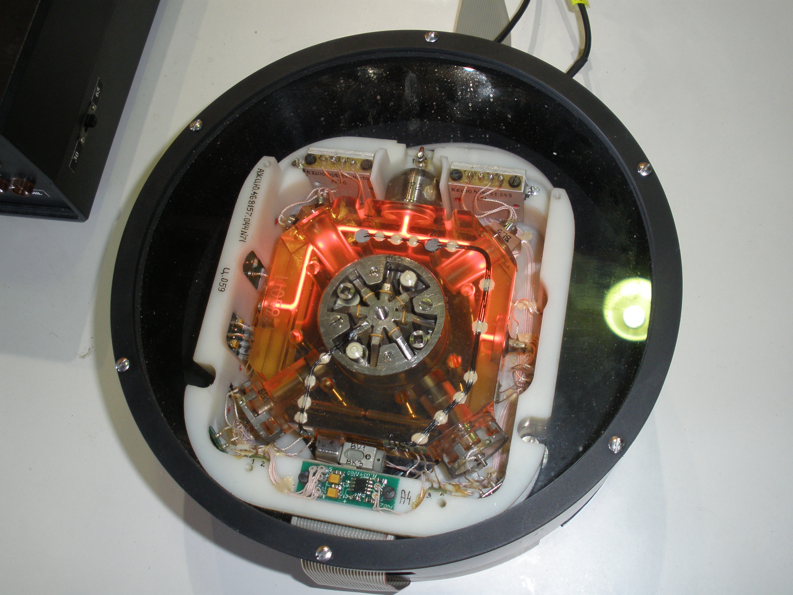
Looks like @zootboy was toying with one of these recently…
https://talk.dallasmakerspace.org/t/who-wants-to-try-an-electric-unicycle/2095

I fear you have a very difficult project ahead of you. IDing and replacing components in a closed design is a tough thing even for an experienced electrical engineer.

Given the number of power-related issues, I think it’s safe to say either the CPU or one of the sensors got damaged. If the CPU was damaged, you’re likely SOL. Even if you could replace it, you wouldn’t be able to replace the software that was programmed into it. If you’re lucky, it’s a sensor that’s bad. You may be able to read the sensors’ data streams with an oscilloscope or logic analyzer.

Either way, you’re definitely in the deep end of the electronics repair pool.

1 Like

Yeah, I agree. I am hoping, based on it’s behavior, that the uc is not damaged. Like I said, it still gives error beeps, attempts to balance sort of, etc. My hope is that it’s a sensor gone bad, or some other components causing a bad signal to the uc. I’m going to attempt some identification today. Luckily, since it is just a knock off clone, they didn’t bother to hide any of the chips under epoxy or anything. That being said, even if it is a sensor, I’m at least in for some SMT rework, which I have not attempted before.

for my uninformed $1 check the gyro. That’s a fast-spinning precision instrument. One good “clunk” as you described and a galled bearing could really screw that baby up in a hurry. I’m betting you’re hearing it try to spin up and fail, followed by codes to that effect.

But that’s pure WAG, so play it like ya see it.

EDIT: this assumes these ACTUALLY use a gyro. I’m (obviously) under the impression they do.

1 Like

People still use mechanical gyros? My smartphone does better than that!

“Better” is subjective. Smartphone tilt sensors don’t actually DO anything with precision, unlike gyro controlled vehicles. But there are certainly more solid state ways to sense tilt. As stated, I do not know how this particular device works.

1 Like

The only gyro in this thing is a MEMS device. Will update more later with part numbers. I had good luck today identifying chips.

1 Like

MEMS --> micro electro mechanical systems.

Electronics are great, but you still eventually need an actual mechanical object to interact with the real world.

Not for this bad boy…

1 Like

Ah, yeah good point. I really just meant it’s gyro is in an IC. Not a large gyro that does any balancing.

Yeah, it definitely doesn’t have one of those!

In fairness, neither does my cell phone.

1 Like

In fairness, modern gyros don’t generally “do balancing”. They provide measurements for other equipment to balance. And now that Richard and you have agreed that, despite the picture of the impressive unit, neither of you has one, what DOES this little guy have?

This is why I’m willing to look stupid; I had no idea such things existed, and I’m still wondering how devices like the uniwheel actually do their job. “It has some sensors and a CPU” won’t cut it, either, since that’s what most articles say…
:smiley:
Thank you for doing this. I’m hoping to learn even more vicariously!

Yeah, makes sense. I initially thought this thing had some sort of large mechanical gyro, so I thought that is what you meant. Not sure that I understood you correctly. Anyway these mems gyroscopes are pretty cool looking… Gyro

Not large, but still essential mechanical.

True, I guess I need to find a better descriptor than mechanical.

1 Like

How about ‘traditional gyro’?

Ah, nuances of language…
As far as I know, pretty much every navigational instrument since the 1950’s/60’s has used gyroscopes to offer electronic feedback to computer control systems to assist and/or automate navigation. These look just like the ones you used as a kid with a string, except they are powered, have serious bearings, and spin much faster and to set speeds. Largely, though, they’re about the same size (somewhere between 2" diameter and 12" diameter, depending on lots of things) and do the same thing: maintain orientation, creating measurable resistance when moved.
In 2006, this is largely still how the Segway worked, as far as I can tell. It makes sense that, since that doorway was kicked open, need for smaller, cheaper gyroscopic instruments would cause an eruption in the tech with the expected miniaturization and trend toward solid-state to improve reliability and reduce power consumption.
These are an interesting mix of traditional but downsized tech, presumably to keep it cheap, unlike the non-mechanical laser device Richard posted up.

At any rate, and however we settle the syntax, thank you for the info. This is cool!

Traditional gyroscopes, those spinning disk devices, work on the principle of the conservation of angular momentum. MEMS units work on the principle of inertia (a cantilever made of conductive material bends slightly in response to motion).

1 Like